Abstract
A completions engineer sits in the data van, reviewing pressure response records alongside microseismic cloud mapping during a 2019 Canadian multi-stage job. Pressure data collected over a roughly 72-hour post-treatment window streams across the monitors, revealing subtle leak-off signatures and pressure decay rates. The central technical concern emerges immediately: determining when hydraulic fracture height growth remains contained within the intended interval, and when it creates credible pathways for out-of-zone fluid migration. This analysis focuses strictly on subsurface mechanisms, diagnostic evidence, and operational controls rather than broad claims about environmental outcome frequency.
Technical Context and Study Question
Fracture height growth dictates the success of stimulation in unconventional reservoirs. The treatment must contact sufficient reservoir volume without connecting to non-target formations, aquifers, depleted intervals, or legacy wellbores. A critical distinction exists between fracture height growth and out-of-zone fluid migration. Height growth represents a fracture geometry outcome—a physical extension of the rock failure. Migration requires a connected pathway, a sustained pressure drive, and a transmissive medium to move fluid from the injection zone to a separate receptor.
Evaluations of stress contrast thresholds between roughly 150 and 400 psi highlight a gap in predicting vertical propagation. Near 150 psi, high net treating pressures easily overcome the barrier, leading to vertical breakthrough. Approaching 400 psi, the barrier becomes highly competent, forcing the fracture network to dilate horizontally and maximize reservoir contact. The primary study question asks: which geological, mechanical, and operational conditions increase the likelihood that treatment energy propagates vertically beyond the intended zone?
Methodology
Synthesizing technical evidence requires strict categorization of subsurface data. Evidence categories drawn from wells drilled between 2016 and 2021 form the basis of this evaluation. This specific timeframe captures the industry transition toward higher intensity completions and hybrid fluid systems. The review encompasses several distinct data streams:
- Geomechanical models derived from dipole sonic logs and core testing.
- Treatment pressure data capturing net pressure evolution.
- Microseismic interpretation focusing on event density and spatial distribution.
- Tracer diagnostics confirming fluid presence in offset wellbores.
- Well integrity records detailing cement bond quality.
Evaluating this evidence demands separating direct observations from inferred fracture geometry. Operational anomalies must be distinguished from confirmed fluid migration pathways. While diagnostic tools provide robust datasets, interpretation inherently relies on calibrated velocity models that carry a degree of spatial uncertainty. This qualifier ensures that inferred data is not treated as absolute physical measurement.
Geomechanical Controls on Fracture Height Growth
Primary, proven containment controls dictate vertical fracture propagation. Minimum horizontal stress contrast, elastic property contrast, fracture toughness, interface slip tendency, and pore-pressure gradients govern the behavior of the fracture tip. Bed thickness mapped at roughly 5-15 m intervals provides the structural framework for these geomechanical barriers. A 5-meter bounding layer might arrest a low-rate stage but fail under high-rate, high-viscosity injection. Conversely, a 15-meter bed provides a robust buffer against aggressive stimulation designs.
Lithologic layering plays a dual role in fracture mechanics. Shale, siltstone, tight sandstone, carbonate stringers, and mechanically weak bedding planes can either arrest vertical growth or divert fracture complexity. The outcome depends heavily on the local stress state and cementation. Pre-existing discontinuities alter the fracture path. Natural fractures and faults create pressure communication or act as barriers if sealed. Containment varies with local fault orientation, leaving an open question regarding the predictability of shear slip during high-rate injection.
Field Note: Mapping bed thickness at high resolution is critical for identifying subtle mechanical interfaces that arrest vertical growth before it breaches the target zone.
Key Findings
Three primary findings emerge from the subsurface data. First, fracture height growth is not inherently equivalent to harmful migration. The critical issue remains whether the induced or reactivated pathway stays conductive and connected to a sensitive receptor or non-target interval.
Second, strong stress contrast and laterally continuous competent barriers generally support containment. Local discontinuities, pressure depletion, and fault architecture reduce confidence in these barriers. A legacy well review completed within about a month pre-stimulation mitigates the risk of intersecting compromised wellbores, ensuring that recent offset activity is accounted for in the risk model.
Third, treatment design directly affects vertical growth. Net pressure, fluid viscosity, rate, stage spacing, cluster efficiency, and proppant placement dictate the energy available for vertical propagation. Aggressive designs increase height growth where barriers are weak, necessitating careful optimization of the pump schedule.
Limitations and Boundary Conditions
Microseismic clouds do not provide exact fracture width, proppant distribution, or fluid volume placement without supporting calibration. Array geometry spacing of roughly 300-800 m inherently limits the resolution of event locations, particularly in the vertical axis. The absence of detected events above a barrier does not constitute proof of zero fracture growth. Detection thresholds, velocity models, and ambient noise conditions heavily influence interpretation.
Crucially, this framework applies only to stress-barrier dominated clastic sequences. Extrapolating these containment principles to highly naturally fractured carbonates introduces significant error.
Important: Microseismic data alone fails to confirm fluid migration in depleted zones.
Monitoring and Diagnostic Evidence
Diagnostic methods offer varying degrees of certainty regarding fracture geometry. Microseismic monitoring, distributed acoustic sensing (DAS), distributed temperature sensing (DTS), tracers, production chemistry, and offset-well surveillance form the diagnostic toolkit. Pressure interference tests run at roughly 6-hour intervals provide direct evidence of inter-well communication, capturing the transient pressure wave before boundary-dominated flow begins.
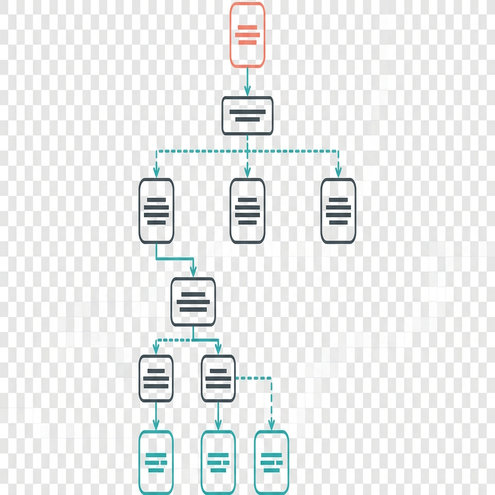
Each method possesses distinct capabilities and blind spots. DAS and DTS identify fluid allocation across clusters but struggle to quantify vertical reach far from the wellbore. Tracers confirm connectivity but cannot map the specific pathway. Demonstrate findings from the University of Calgary, integrating multiple diagnostic streams prevents over-reliance on a single technology. The SPE paper by Fisher and Warpinski provides foundational real-world fracture height observations, reinforcing the need for multi-disciplinary data integration.
Operational Implications for Stage Design and Risk Control
Translating diagnostic findings into design actions requires agility. When containment risk elevates, engineers adjust stage length, cluster spacing, pump schedules, fluid systems, proppant loading, and pressure limits. A stage redesign cycle completed in about 48 hours follows a strict sequence:
- Download and process high-frequency pressure data from the previous pad.
- Update the geomechanical model with observed net pressure responses.
- Adjust cluster spacing and proppant loading to mitigate identified height growth risks.
- Transmit the revised pump schedule to the field execution team.
Pre-job controls establish the foundation for safe execution. Teams map offset wells, identify abandoned wellbores, review cement and casing records, evaluate stress barriers, and flag faults or karst-prone intervals. Regulatory frameworks, such as AER Directive 083: Hydraulic Fracturing – Subsurface Integrity, mandate rigorous subsurface evaluation prior to pumping. Real-time controls involve monitoring treating pressure, unexpected pressure communication, offset-well response, and deviations from modeled behavior.
Pre-Stage Decision Gate
Execution relies on strict operational boundaries. Stop-work thresholds set near a 250 psi deviation trigger immediate review protocols. If treating pressures drop unexpectedly by this margin, indicating a potential breach of a containment barrier or intersection with a conductive fault, pumping halts. The engineering team evaluates the pressure derivative, cross-references offset well gauges, and determines if the stage requires immediate modification, diversion, or abandonment.
Bottom Line: Establishing rigid pressure deviation thresholds prevents runaway fracture growth into non-target zones.
Field Execution
At 2:00 AM on the pad, the wireline crew finishes rigging down while the completions engineer isolates the previous stage. The pressure gauges on the offset observation well hold steady, showing zero anomalous response. The engineer logs the final treating pressure, notes the successful containment below the overlying siltstone barrier, and signals the pump operator to initiate the next sequence.