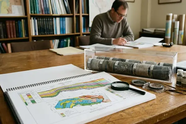
Abstract
Pore-throat architecture is the governing variable for forecasting carbonate flow capacity. Every log-derived reservoir-quality call should be tested against that premise. This article serves as a formal summary of a technical paper on petrophysical controls in carbonate reservoirs, rather than a new field-data study. Reservoir quality is defined here as the combined capacity to store hydrocarbons, transmit fluids, and remain predictable under scale transition from plug to log to reservoir model. Core-to-log calibration steps are drawn from intervals spanning roughly 0.5 m to 3 m vertical resolution.
Introduction: Why Carbonate Reservoir Quality Resists Simple Porosity Ranking
Carbonate reservoirs are commonly misranked when porosity is treated as the dominant quality indicator. Storage capacity and flow capacity operate independently in these systems—a distinction that becomes critical during dynamic modeling. Interparticle pores, moldic pores, vugs, microporosity, fractures, and stylolite-related pathways contribute differently to production behavior.
The scale problem complicates this evaluation. Plug measurements capture centimeter-scale features while logs integrate over roughly 0.3 m to 1.2 m intervals. A high-porosity zone identified on a density log may represent isolated vugs that offer zero connected transmissibility, while a low-porosity zone might contain a micro-fracture network capable of sustained flow.
Methodology: Integrated Core, Log, and Thin-Section Evaluation
Inputs are ordered from core description through wireline logs to follow standard academic sequence. API RP 40, revised in 1998, serves as a common procedural anchor rather than a mandatory protocol.
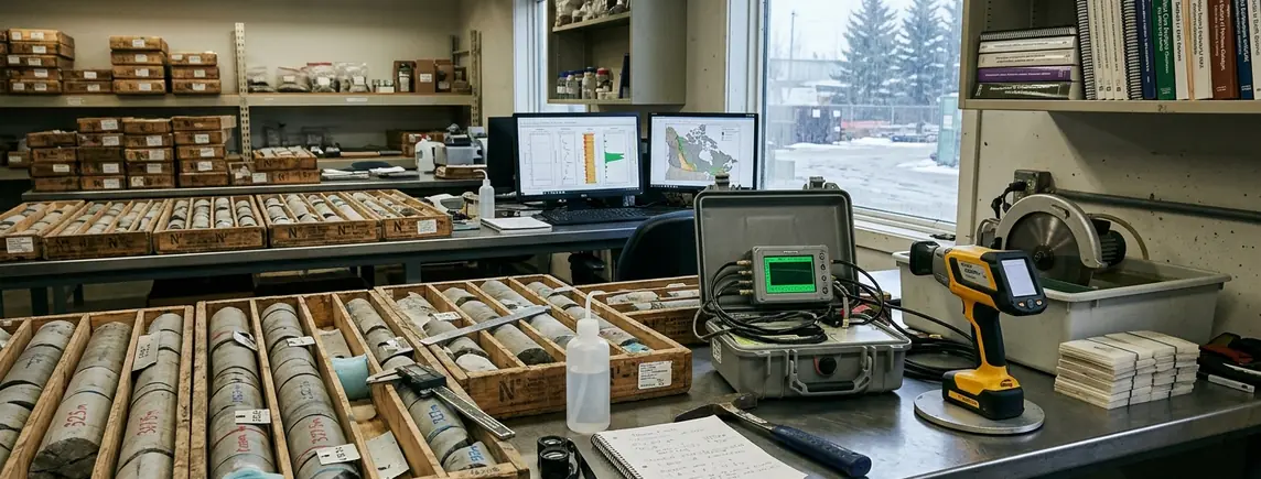
The first input requires detailed core description. This includes lithofacies, depositional texture, visible vugs, fractures, cement fabrics, stylolites, and evidence of dissolution or dolomitization. The second input involves routine core analysis performed at ambient conditions, then up to about 4000 psi net confining stress. Interpretation depends heavily on sample condition, cleaning, stress state, and representativeness.
Control 1: Porosity Partitioning and Pore-Throat Geometry
Total porosity is insufficient in carbonate formations without partitioning the pore system by type and connectivity. Interparticle porosity, intraparticle porosity, moldic porosity, vuggy porosity, microporosity, and fracture porosity must be compared in terms of their likely contribution to flow.
Pore throats act as the controlling link between storage and permeability. Research conducted at the University of Calgary indicates that isolated vugs demonstrably inflate porosity without raising connected transmissibility. Mercury-injection data collected on 1.5-inch plugs from selected depth stations confirm this diagnostic separation for intervals sharing similar total pore volumes.
Control 2: Saturation, Wettability, and Resistivity Response
Water saturation estimates in carbonates are affected by pore geometry, wettability, microporosity, clay content where present, and conductive fluids. Archie’s original resistivity-log paper, published in 1942, remains a foundational reference for clean formations. Carbonate heterogeneity often requires local calibration of cementation and saturation exponents from core electrical measurements.
Electrical property measurements run at formation temperature between roughly 60 °C and 90 °C provide this baseline. Resistivity alone is insufficient when pore type, invasion effects, and log resolution remain unresolved. Microporosity frequently explains elevated water saturation in otherwise productive zones.
Control 3: Diagenesis, Depositional Fabric, and Rock Typing
Depositional texture establishes the initial pore framework. Diagenesis can either preserve, enhance, redistribute, or destroy reservoir quality. Major diagenetic processes include cementation, compaction, pressure solution, dissolution, dolomitization, recrystallization, and anhydrite or calcite occlusion.
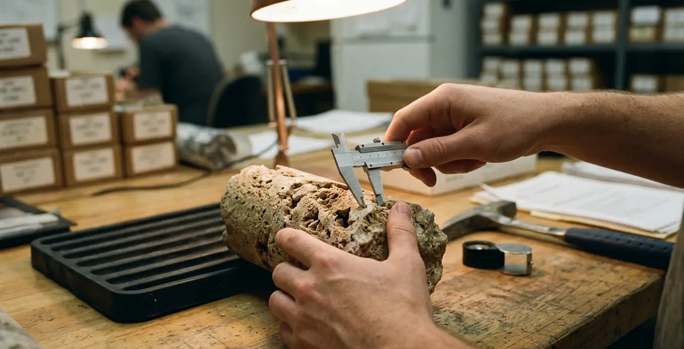
Two intervals with similar lithofacies may diverge petrophysically if one has connected dissolution-enhanced pores and the other has cement-occluded pore throats. Thin-section descriptions recorded at 50× to 200× magnification for cement and pore occlusion reveal these microscopic divergences. Rock typing bridges fabric description and flow-unit prediction. Its validity is tied to reproducibility across core, log, and dynamic observations rather than universal categories.
Key Findings: Predictors That Best Separate Flow Units
Synthesized from peer-reviewed carbonate petrophysics literature, the data reveal distinct patterns in flow unit separation.
Bottom Line: Connected pore-throat systems are stronger indicators of reservoir quality than gross pore volume alone.
Pore-type classification improves the interpretation of porosity-permeability scatter in carbonate core datasets. Capillary pressure curves acquired on samples from 10 m to 40 m cored intervals demonstrate that pore-type classification consistently reduces this scatter.
Limitations: Where the Interpretation Can Fail
Core plugs miss fractures larger than sample diameter in vuggy intervals. Log averaging masks thin high-permeability streaks when bed thickness falls below about 0.3 m.
Field Note: Laboratory permeability measured at 800 psi often misrepresents the in-situ effective stress of roughly 2500–4500 psi.
While the 2007 edition of Lucia's monograph provides a robust framework for rock fabric classification, field-specific diagenetic overprints often necessitate localized adjustments to these global models.
Important: Do not convert a carbonate rock type into a completion decision unless the evidence chain reaches from pore system to log response to operational objective.
Implementation: Cutoffs, Ranking, and Model Inputs
Workflow steps move sequentially from lithofacies assignment to rock-type flags. Cutoffs are treated as field-specific hypotheses rather than constants. Log calibration is performed over 2 m to 5 m sliding windows matching core depth registration.
Worked Example: Three Carbonate Intervals
Three carbonate intervals illustrate relative ranking without numeric invention. Interval A features interparticle porosity with minimal cementation. Interval B contains abundant isolated moldic pores. Interval C exhibits extensive microporosity.
Borehole image logs processed at 0.1 m vertical sampling interval identify the lack of connected fractures in Interval B. Core descriptions confirm Interval A possesses the largest pore throats. Interval C shows high water saturation on resistivity logs due to microporosity—yet produces dry hydrocarbons.
The ranking places Interval A as the primary flow unit. Interval C acts as a secondary contributor requiring specific completion strategies to overcome high capillary entry pressures. Interval B functions strictly as a storage-only zone, bypassed during dynamic flow.