Quick Nav
- Why the carbonate-clastic comparison changes reservoir decisions
- Architectural building blocks and flow units
- Depositional controls in transported versus produced sediment systems
- Pore architecture, heterogeneity, and prediction risk
- Minimum datasets before modeling
- Facies, property, and connectivity implications
- Technical review checklist
- Copyable screening workflow for a new interval
Why This Comparison Changes the Reservoir Decision
Carbonate and clastic reservoirs can look deceptively similar on a structure map. A pay flag, a porosity cutoff, and a net-to-gross calculation may sit in the same spreadsheet. The reservoir architecture behind those numbers may not behave the same way at all.
Misreading that architecture changes practical decisions: where a horizontal well lands, which interval counts as connected net pay, whether pressure support should communicate across a mapped body, and how much confidence a simulation case deserves before a development meeting.
Reservoir architecture means the three-dimensional arrangement of depositional bodies, pore systems, barriers, baffles, and flow units. It is not simply lithology. A sandstone channel belt and a carbonate shoal can both carry reservoir-quality rock, but their continuity, vertical leakage, and pore-scale controls may follow different rules.
This comparison is written for interpreters who move between stratigraphy, sedimentology, geophysics, petrophysics, and reservoir engineering. The useful question is not whether one reservoir type is more complex. It is which part of the architecture carries the uncertainty that will change the next technical decision.
Architectural Building Blocks: Bodies, Boundaries, and Flow Units
Clastic elements preserve transport logic
Clastic reservoirs usually start with sediment moved from somewhere else. Channels, mouth bars, shoreface sandstones, turbidite lobes, levees, floodplain mudstones, and sequence-bounding surfaces all record a history of sediment supply, transport direction, and accommodation.
That record gives the interpreter handles. Grain-size trends, cross-bedding direction, upward-fining channel fills, upward-coarsening shoreface packages, and compensational stacking can be mapped into depositional elements. The mapping still requires discipline, but the bodies often retain the geometry of movement.
In the WCSB seismic volumes used for this comparison, channel-belt widths averaged roughly 180-420 m. That range matters in a model review because a channel object copied from a distant deltaic analogue can quietly stretch connectivity beyond what the local stratigraphy supports. Channel-stacking statistics derived from Gulf Coast basins produce incorrect body dimensions when applied to tidally influenced WCSB sandstones.
Carbonate elements add production and early alteration
Carbonate reservoirs often build where sediment forms in place. Shoals, reefs, buildups, lagoons, tidal flats, slope aprons, hardgrounds, exposure surfaces, and cemented zones form a different architectural vocabulary.
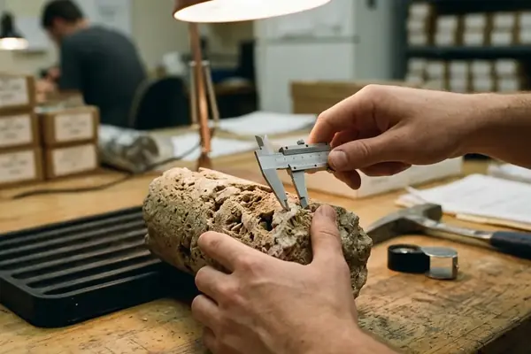
A cross-check against roughly a dozen cored WCSB intervals put shoals and hardgrounds near the top of the working list because those features directly controlled flow-unit boundaries. In core recovery intervals of about 0.8 to 2.3 m, hardground cementation reduced vertical permeability below roughly 0.05 mD. That is not a decorative boundary in a core photo. It is a modeling boundary unless dynamic data argues otherwise.
Field Note: In technical reviews, clastic elements usually need geometry control first. Carbonate elements often need fabric and diagenetic control before their geometry means much.
Stratigraphic surfaces still matter in both settings. For terminology and surface hierarchy, the International Stratigraphic Guide remains a useful reference point, especially when several disciplines use different names for the same boundary.
Depositional Controls: Transport-Dominated Versus Production-Dominated Systems
The working hypothesis is simple: clastic prediction starts with sediment routing, while carbonate prediction starts with sediment production and modification. The method is to ask what process had to occur before reservoir-quality rock could exist.
Clastic control set
For clastics, the main controls are sediment source, transport energy, basin physiography, sea-level accommodation, climate, and routing pathway. A sandstone body must first be supplied, then transported, then trapped or preserved in a stratigraphic position where later erosion did not remove it.
- Source: controls sand volume, mineralogy, and mud content.
- Transport energy: sorts grains and sets bedform architecture.
- Basin physiography: directs fairways and local accommodation.
- Relative sea level: changes shoreline trajectory, incision, and preservation.
- Climate: influences discharge style, sediment load, and weathering products.
Carbonate control set
For carbonates, the main controls are factory type, water depth, light penetration, salinity, oxygenation, nutrient level, wave energy, and platform position. Sediment may form on the platform top, at the margin, in protected lagoons, or on slope aprons. Reservoir quality then depends on how that sediment was stabilized, cemented, dissolved, fractured, or compacted.
The predictive contrast is sharp. Clastic prediction often asks where sand moved and where it became trapped. Carbonate prediction asks where sediment was produced, preserved, cemented, or dissolved. A platform-margin shoal and a fluvial channel may both appear as high-energy deposits, but one carries a strong biological and diagenetic filter that the other does not.
The limitation sits at mixed systems. Mixed carbonate-clastic intervals require separate mapping of each lithology before any shared flow-unit scheme is applied. Treating the package as one blended facies association usually hides the actual control on flow.
Pore Architecture and Heterogeneity: Where the Biggest Prediction Risk Sits
Start with the data. Thin-section counts from the sampling campaign recorded roughly 18-34% microporosity coexisting with 2-7 mm vugs. In selected shoreface sandstones, deformation-band frequency reached about 4-9 per meter. Both observations matter, but they do not create the same modeling problem.
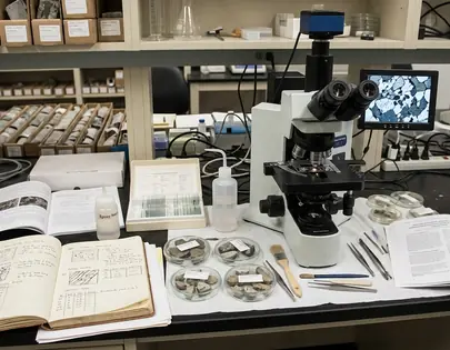
Clastic pore systems commonly revolve around intergranular porosity, compaction, cement distribution, clay content, grain sorting, and permeability anisotropy aligned with depositional fabric. A clean, well-sorted shoreface sandstone tends to offer a more direct line from texture to permeability than a muddy heterolithic interval. Deformation bands can interrupt that relationship, especially where strain localizes in porous sand.
Carbonate pore systems bring a wider pore vocabulary: interparticle, intraparticle, moldic, vuggy, fracture, fenestral, and microporous fabrics. The diagenetic overprint can reorganize flow at a scale smaller than the seismic bin and larger than a plug. That is an awkward scale for prediction.
The most costly mistake is assuming that high porosity and high permeability remain coupled. In the tested carbonate plugs reviewed here, 9 of 11 exhibited capillary entry pressures differing by more than two orders of magnitude within the same comparison set. Large vugs, microporosity, cemented intervals, and fractures can sit close together. Carbonate porosity and permeability may therefore decouple more dramatically than in many sandstone reservoirs.
Important: Models trained predominantly on deltaic sandstones routinely under-predict touching-vug connectivity in platform-margin carbonates.
One qualifier is worth keeping visible: these observations come from selected WCSB intervals and specific sampling campaigns, so they should constrain analogue choice rather than replace field-specific calibration.
Data Requirements: What Each Reservoir Type Demands Before Modeling
The gap between a map-ready interpretation and a simulation-ready model often appears in the data checklist. The seismic interpreter may have a mappable body. The petrophysicist may have a porosity curve. The modeler still needs to know whether those observations describe the same flow unit.
Minimum clastic dataset
- Core description tied to depositional facies and bounding surfaces
- Grain-size trends and sedimentary structures
- Wireline log motifs calibrated to core
- Seismic geomorphology where resolution supports body mapping
- Stratigraphic surfaces and sequence boundaries
- Pressure data across interpreted compartments
- Production response from analogous intervals or early wells
Minimum carbonate dataset
- Detailed core facies with fabric, texture, and exposure features
- Thin-section petrography placed early in the workflow
- Image logs for fracture and bedding orientation
- Pore-type classification rather than porosity class alone
- Diagenetic history, including cementation and dissolution timing
- Fracture observations separated from vuggy fabric
- Capillary pressure measurements and saturation-height calibration
- Seismic attributes tested against core and log evidence
- Dynamic tests where static connectivity remains ambiguous
Thin-section petrography should not wait until after the log interpretation has hardened into zones. Review of roughly two dozen wells placed petrography ahead of image-log analysis because pore-type misclassification from logs alone altered saturation-height functions. Capillary pressure curves in that workflow were acquired at about 0.5 MPa increments between 0.1 and 20 MPa, which made pore-system separation visible where conventional log tracks looked similar.
Seismic attributes still help, but they need scale awareness. Take a concrete case: attribute extraction windows of 8-12 ms two-way time may support architectural trends across a platform-margin interval, yet the same windows will not uniquely resolve whether a bright event reflects touching-vug porosity, early cementation, or fabric-selective dissolution. Two wells drilled into that same attribute anomaly can return very different pore types, which is why core carries special weight in carbonates.
Modeling Implications: Facies, Properties, and Connectivity
The conclusion comes first: carbonate and clastic reservoirs should not receive the same default modeling recipe just because both have facies codes. The codes may represent different kinds of geological control.
Facies modeling
Channelized clastics may suit object-based or process-informed bodies when well control, seismic geomorphology, and stratigraphic surfaces support that choice. A point-bar, tidal channel, or turbidite lobe has a body logic that can be parameterized, tested, and adjusted against thickness and continuity evidence.
Carbonates often need hierarchical facies, diagenetic overprints, fracture domains, or multiple property trends within the same depositional unit. A shoal grainstone may behave as more than one rock type if cement occludes part of the fabric and dissolution opens another part.
Property modeling
Clastic property models often lean on grain size, shale volume, depositional element, and compaction trend. These inputs do not remove uncertainty, but they keep the property model tied to sedimentological causes.
Carbonate property models commonly need pore-type classes, cement zones, leached intervals, fracture sets, and fabric-based rock types. If those inputs collapse into a single porosity-permeability transform, the model may look tidy and still miss the actual flow paths.
Connectivity
Clastic connectivity may depend on sand-body stacking, mudstone continuity, channel amalgamation, and shoreline trajectory. Carbonate connectivity may depend on touching vugs, fractures, karst zones, cemented barriers, and platform-margin architecture.
Bottom Line: In clastics, ask whether sand bodies touch. In carbonates, ask whether the pore systems that transmit flow touch.
Side-by-Side Comparison for Technical Reviews
The table below works best as a review checklist. It should not become a classification shortcut. A tidally influenced sandstone and a dolomitized shoal can both break the simplified tendencies if the evidence points that way.
| Attribute | Clastic tendency | Carbonate tendency | Interpretation consequence |
|---|---|---|---|
| Primary control | Sediment source, transport, accommodation, routing | Carbonate factory, platform position, water chemistry, diagenesis | Choose analogues from process match, not lithology name alone |
| Common architectural elements | Channels, mouth bars, shorefaces, turbidite lobes, levees, floodplain mudstones | Shoals, reefs, buildups, lagoons, tidal flats, slope aprons, hardgrounds | Map body geometry and boundary type separately |
| Pore-system predictability | Often tied to texture, sorting, clay content, and compaction | Strongly affected by pore type, cement, dissolution, and fractures | Do not transfer sandstone porosity-permeability habits into carbonate models |
| Dominant baffles | Mudstones, shale drapes, heterolithic beds, deformation bands | Cemented zones, hardgrounds, tight mud-rich carbonates, exposure surfaces | Test vertical communication with boundary-specific evidence |
| Seismic expression | May show geomorphic bodies where resolution is adequate | May show platform architecture, margins, or attribute trends | Separate mappable form from pore-system prediction |
| Core dependency | High for facies calibration and grain-size trends | Very high for pore type, cement, dissolution, and fabric classification | Carbonate logs need core and petrography earlier in the workflow |
| Upscaling risk | Sand-body dimensions and mudstone continuity | Vug-fracture interaction and small-scale cement barriers | Upscale after defining the flow mechanism |
| Common modeling mistake | Using non-local channel dimensions without stratigraphic testing | Using one porosity-permeability transform across several pore systems | Build uncertainty cases around the controlling architecture |
Worked Example: A Copyable Screening Workflow for a New Interval
Use this example in a new technical review. The interval has two cored wells, image logs in one well, sparse seismic control, and uncertain reservoir continuity. The team needs a screening decision before building a full static model.
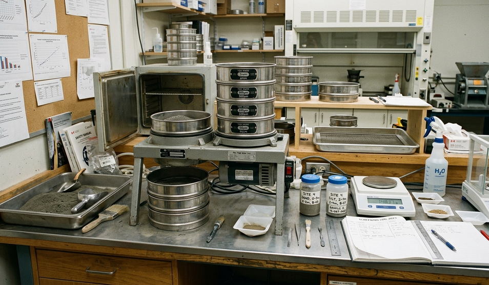
- Lay out the evidence by scale. Put core facies, sedimentary structures, pore descriptions, cement observations, fracture picks, log motifs, pressure points, and seismic picks on one page. Do not start with a facies model.
- Test what reservoir quality follows. In Well 1, mark every reservoir-quality sample against depositional texture, shale content, pore type, fracture intensity, and cement zones. In Well 2, repeat the same marks even if the core is shorter. If porosity tracks grain size and shale volume, the first-order architecture may be clastic-style. If similar textures split into different permeability classes because of vugs, cement, or fractures, the first-order architecture may be carbonate-style.
- Build two competing hypotheses only if the observations justify both. Hypothesis A is a clastic-style body-continuity case: reservoir quality follows connected depositional bodies, and barriers are mainly mud-rich or heterolithic intervals. Hypothesis B is a carbonate-style pore-overprint case: depositional bodies provide the container, but flow follows pore type, fractures, leached zones, and cement boundaries.
- Assign one decisive test to each hypothesis. For Hypothesis A, compare thickness trends, log motifs, and any seismic geomorphology against expected body width and stacking. For Hypothesis B, compare thin sections, image-log fractures, capillary pressure behavior, and core-scale cement boundaries against the permeability distribution.
- Make the first model case deliberately small. Build a pilot grid around the two wells. In the clastic-style case, model bodies and mudstone baffles first, then distribute properties by grain size and shale content. In the carbonate-style case, model depositional containers first, then overprint pore-type classes, cemented intervals, and fracture domains.
- Write the decision in one sentence. For example: “Continuity will be modeled as a channelized sand-body problem unless thin sections from the upper interval show vuggy or cement-controlled permeability independent of depositional texture.” That sentence can go directly into the model-design note for the next University of Calgary core workshop or conference technical review.