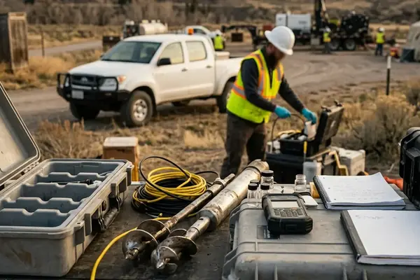
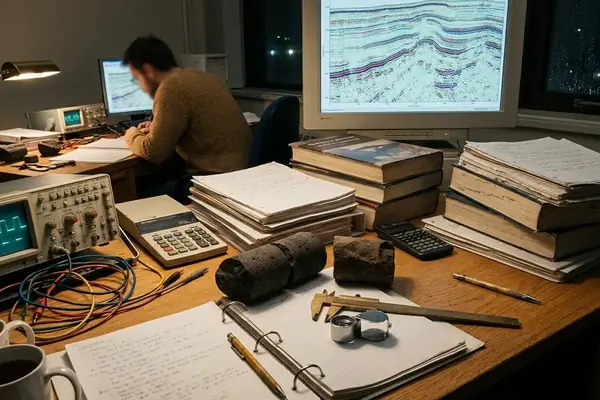
From Check-Shot Control to Reservoir-Scale VSP
Vertical seismic profiling used to sit in the check-shot corner of the program: run the tool, pick first breaks, tighten the time-depth curve, move on.
That role still matters. But complex reservoirs have pushed VSP into a larger job. When surface seismic struggles with structural dip, lateral velocity change, anisotropy, fault shadowing, multiples, and weak well ties, the borehole becomes more than a calibration point. It becomes the place where measured depth, travel time, lithology, and seismic response meet under controlled geometry.
The case used here follows that shift. Surface seismic gave regional continuity, yet the reservoir-scale interpretation near the well stayed unsettled. The workflow therefore moved from surface-only interpretation to a borehole-constrained design: define the uncertainty, choose the VSP mode, process the wavefield carefully, and report the result as a drilling or completion decision.
This is the kind of problem that belongs in a GeoConvention technical session or a University of Calgary reservoir characterization discussion: not VSP as a display product, but VSP as a decision tool.
Prior work, gap, proposed approach
Prior work gave the team a usable surface-seismic framework and a conventional synthetic tie. The gap sat at the well scale, where horizon position and fault geometry could not carry the next operational choice. The proposed approach was narrow by design: use borehole seismic only where it could reduce uncertainty around the reservoir top, the nearby fault plane, and the planned completion interval.
Bottom Line: A modern VSP earns its place when it changes an interpretation decision, not when it merely decorates a seismic report.
Challenge: A Reservoir Where Surface Seismic Could Not Carry the Interpretation
The reservoir setting was structurally and stratigraphically awkward. Existing well logs and surface seismic showed reflectors dipping at about 35 degrees, two compartmentalizing faults within roughly 200 m of the pilot well, and lateral velocity variation across the fault block.
The surface volume still did useful work. It mapped the regional trend and kept the broader stratigraphic picture coherent. It did not resolve the well-scale questions cleanly enough: the reservoir-top tie carried a 12 ms two-way-time mistie, and the velocity field changed by roughly 180 m/s laterally across the fault block.
Data presentation, interpretation, open question
- Observed setting: steep dips, two nearby faults, and lateral velocity variation around the pilot well.
- Interpretation risk: horizon ties and fault placement could shift the mapped reservoir contact.
- Operational exposure: sidetrack planning, completion interval selection, reserves mapping, and appraisal-well placement all depended on the same local model.
The open question was not whether the surface seismic was good or bad. It was whether the interpretation near the well could support a specific decision before the next drilling window closed.
In this case, it could not.
Why VSP Was Chosen Instead of More Surface-Seismic Reprocessing
The technical reason was straightforward: VSP records the seismic wavefield inside the borehole. That gives a direct link between measured depth, travel time, lithology, sonic and density logs, and the surface-seismic response. Reprocessing surface seismic may improve continuity, but it does not create a new downhole measurement.
The selected design used zero-offset VSP for time-depth calibration and added a single offset source at about 800 m to illuminate the nearest fault plane. Surface access limited the walkaway line length to roughly 1200 m, so the team did not pretend the survey could solve every regional imaging problem.
VSP mode selection
- Zero-offset VSP: best suited to check-shot correction, first-break control, corridor stacking, and well-tie improvement.
- Offset VSP: useful where the question involves dipping beds, near-well faults, or directional illumination from one chosen azimuth.
- Walkaway VSP: suited to lateral velocity variation, anisotropy estimation, and reflector-position testing along an accessible line.
- 3D VSP: most appropriate when fault geometry or reservoir architecture requires areal illumination around the borehole.
Three-component geophones were clamped at 8 levels, which allowed tool orientation and wavefield separation to become part of the interpretation workflow rather than post-acquisition housekeeping.
Field Note: In thrust terrain, corridor stack ties degrade when source offset exceeds about 1200 m. That limit shaped the survey geometry instead of being discovered during interpretation.
Solution Part 1: Design the Survey Around the Geological Question
The design principle was simple: begin with the reservoir uncertainty, then choose geometry. Not the other way around.
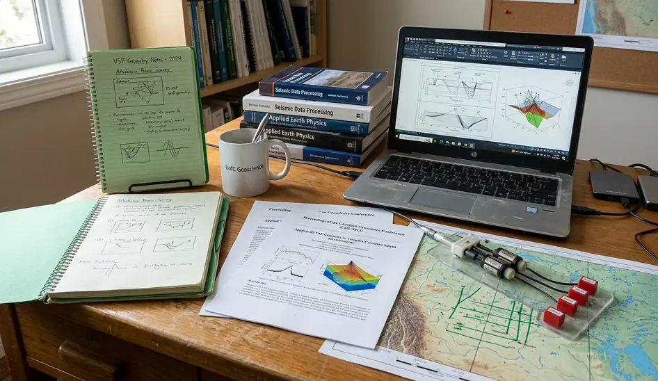
The target was to image the reservoir top within about 150 m of the wellbore. That requirement drove the source layout, receiver interval, receiver spacing, and component selection. Receiver levels were spaced at 15 m across a 450 m open-hole interval. The recording window was 4 s at a 1 ms sample rate, and source activation was restricted to daylight hours during a 14-hour operating period.
Hypothesis, methodology, findings
Hypothesis: if the borehole receivers sampled the target interval closely enough, the VSP would reduce the time-depth ambiguity at the reservoir top and improve the local fault interpretation.
Methodology: deploy clamped downhole geophones, verify coupling at each receiver station, run three-component acquisition, and check depth control before accepting the level sequence. The near-offset source supported time-depth calibration. The far-offset azimuth aligned with the dominant structural dip, so the survey could test the nearest fault plane instead of merely repeating a check-shot.
Findings: the geometry matched the decision. It did not attempt regional imaging beyond the VSP illumination footprint. These numbers remain local to this borehole, receiver layout, and access constraint; they should not be treated as a portable acquisition recipe.
Important: Coupling failure becomes a real risk when borehole deviation exceeds about 55 degrees in shale sections. Receiver coupling checks are not optional in that setting.
Solution Part 2: Process the Borehole Wavefield Before Interpreting It
VSP interpretation starts after the wavefield has been disciplined. Raw borehole records contain useful signal, but also tool-orientation issues, tube waves, downgoing energy, upgoing reflections, and geometry errors that can mislead a reservoir pick.
The processing sequence followed a tight order: geometry verification, first-break picking, tool-orientation correction, wavefield separation, deconvolution, corridor stacking, VSP-CDP transformation, and migration where appropriate. First-break picks were completed within about 36 hours of rig release, which mattered because the sidetrack decision window was short.
Why the order mattered
- Geometry verification protected the measured-depth and source-position basis of the survey.
- First-break picking stabilized the time-depth model and reduced reliance on extrapolated surface-seismic velocities.
- Tool-orientation correction made the three-component data interpretable before wavefield separation.
- Wavefield separation distinguished downgoing energy from upgoing reflections, especially where tube waves contaminated the response.
- Deconvolution used a 120 ms operator to sharpen the reflected wavefield.
- Corridor stacking used a 40 ms window below the first break to improve the well tie.
- VSP-CDP transformation used a 25 m bin size to place reflections into a surface-seismic comparison frame.
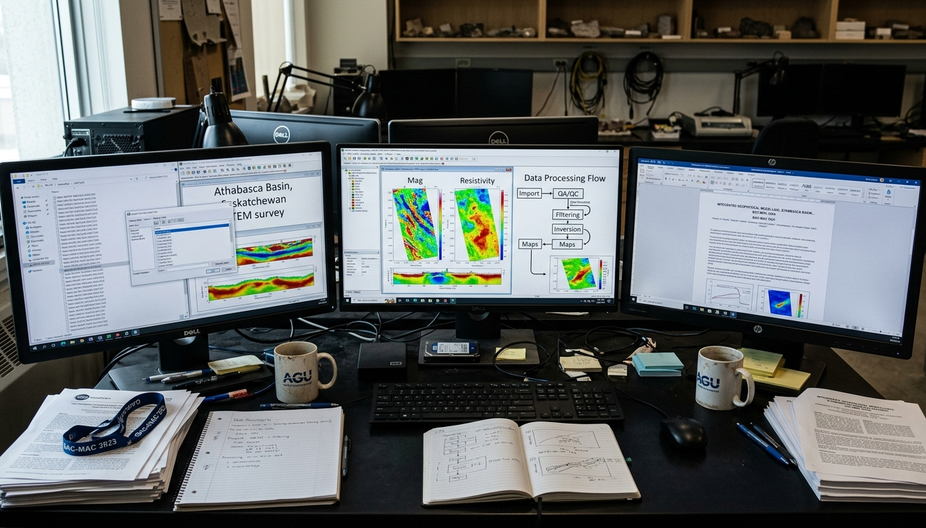
The velocity model was then refined with borehole seismic, sonic logs, density logs, synthetic seismograms, and surface-seismic ties. This is where VSP becomes interpretation work rather than processing work. The corrected time-depth function must still agree with the rocks in the well.
Applications: What the VSP Changed in the Reservoir Model
The useful way to organize VSP applications is by decision type.
Decision applications
- Time-depth calibration: the VSP-derived relationship recalibrated surface-seismic horizons near the well.
- Surface-seismic tie: the synthetic tie residual was reduced to under 4 ms.
- Fault positioning: the interpreted fault intersection moved about 35 m along the well trajectory.
- Stratigraphic correlation: the reservoir top pick shifted by 8 ms after the updated time-depth function was applied.
- Anisotropy correction: the anisotropy parameter delta was revised from about 0.08 to 0.14.
- Near-well reservoir prediction: the planned perforation interval changed after the updated fault and top-reservoir positions were reviewed.
The important move was not the 8 ms shift by itself. It was the chain of consequences: revised reservoir top, adjusted fault intersection, and a different completion interval. That is the interpretation path asset teams can use.
Offset and walkaway VSP also help when steep dips and fault planes suffer from poor surface-seismic illumination. Here, the single offset source gave the interpretation team a focused test of the nearest fault plane rather than a broad survey with unclear accountability.
Results: Report the Decision Impact, Not Just the Processed Section
The project reported results as decision outcomes. That discipline kept the final interpretation from becoming a gallery of processed sections.
- Well tie: the corridor stack and synthetic comparison tightened the reservoir-top tie.
- Velocity model: the lateral velocity issue across the fault block was incorporated into the local time-depth model.
- Horizon pick: the reservoir top was revised to about 2487 m measured depth.
- Fault geometry: the fault position was adjusted roughly 22 m updip.
- Completion plan: the perforation interval changed after the revised top and fault intersection were accepted in the interpretation workshop.
No reserve volumes were reported. The project record contained no production data, so the result stayed where the evidence was strongest: borehole seismic, migrated VSP image, log-seismic correlation, and the drilling/completion decision.
That restraint matters. A VSP can strengthen local calibration, but it does not turn a single well into a field-wide reserves audit.
When a Complex-Reservoir VSP Is Worth the Cost
The screening test should be practical enough for petroleum geologists, geophysicists, reservoir engineers, and asset teams to use in the same room.
In the case reviewed here, the cost range for a single-well zero-offset plus offset survey was roughly 180-240 k CAD. The decision window between acquisition and sidetrack spud was 5 days. Those two facts forced a hard question: will the VSP result change the next well trajectory or completion choice?
Strong use cases
- Poor surface-seismic well tie at the reservoir objective.
- Critical fault uncertainty near a planned well.
- Suspected anisotropy affecting time-depth conversion.
- Steep dips, salt complexity, thrust geometry, or strong lateral velocity variation.
- High-value appraisal or development decisions with a near-term drilling action.
Weak use cases
- No accessible borehole.
- No clear decision for the VSP to support.
- Regional uncertainty beyond the VSP illumination area.
- High receiver-coupling risk that cannot be mitigated.
- Existing check-shot and surface seismic already satisfy the decision tolerance.
Important: VSP improves local calibration only when at least one receiver station lies within the target reservoir interval.
Recommended Next Move and Citations
Citations
- vsp-from-check-shot-to-reservoir-tool: project narrative and acquisition record for the shift from check-shot control to reservoir-scale VSP.
- case-challenge-complex-reservoir-setting: case record for dip, fault proximity, horizon mistie, and lateral velocity variation.
- processing-workflow: processing note for wavefield separation, corridor stack design, deconvolution operator length, and VSP-CDP binning.
- interpretation-applications and case-results: interpretation records for reservoir-top shift, anisotropy revision, fault adjustment, and completion-plan change.
Decision test
The one-page decision test should come before acquisition approval. It needs four lines: the geological uncertainty, the VSP mode, the interpretation product required, and the drilling or completion decision that will change if the result is accepted.
Run the VSP only when that page names a near-well decision and a target interval; otherwise, spend the budget on the interpretation work the asset team can actually use.